CanBot: moving a waste-sorting robot from YOLO v2 to v3
Why the first detector failed on a Raspberry Pi, what changed with YOLO v3 and an Intel NCS2, and why the gripper, not the vision, ended up as the bottleneck.
Rayhan M. Project: Dec 2024 Written 3 min read Source on GitHub
CanBot is an autonomous rover that finds bottles and cans with a camera, picks them up with a 6-DOF arm, and drops them into separate bins. It was an eight-person project for EE297 Intelligent Systems at Maynooth. I worked on two parts: the computer vision (moving the detector to YOLO v3, collecting and labelling the dataset, training, and deploying to the Raspberry Pi) and the rover base.
The design files, kinematics solver and reports are on GitHub. The vision code itself wasn’t preserved after the module, so this post sticks to what was designed and measured.
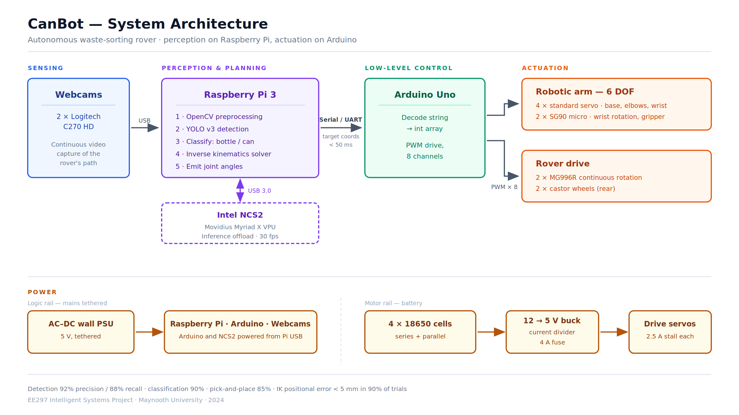
How the pieces talk
The Raspberry Pi does perception and planning. When it detects an object, it sends the target coordinates to an Arduino as a serial string over UART. The Arduino decodes the string and drives eight servos: six on the arm and two continuous-rotation servos on the rover’s wheels. Round-trip latency stayed under 50 ms.
Splitting the work this way keeps each board doing what it’s good at. The Pi has the memory and USB bandwidth for a camera and a neural network accelerator, and the Arduino gives clean, deterministic PWM for the servos.
Why YOLO v2 didn’t survive testing
The team started with YOLO v2. Testing exposed two problems:
- Accuracy collapsed under poor lighting and when an object was partly hidden.
- Speed. Running the Darknet implementation on the Pi’s CPU was too slow for real-time use.
I proposed moving to YOLO v3. Its main architectural change is predicting at three scales instead of one, which helps with small and partly occluded objects: exactly the failure cases we were seeing.
Training the detector
- Data. We combined open-source images with photos we took ourselves, then labelled every image as
bottleorcanin LabelImg. - Split. 70% for training, 20% for the first round of testing, and 10% held back for a second test after fine-tuning.
- Config. I set up Darknet, edited the YOLO v3
.cfgfor two classes with custom anchor boxes, and started from pretrained weights. - Deployment. The trained model ran on a Raspberry Pi 3A with a Logitech C270 webcam, with inference offloaded to an Intel Neural Compute Stick 2 so the network didn’t compete with the Pi’s CPU.
| Metric | Result |
|---|---|
| Detection precision | 92% |
| Recall | 88% |
| Classification accuracy | 90% |
| Inference speed | 30 fps with the NCS2 |
Reflective cans remained the main source of misclassification. Contrast normalisation during preprocessing helped, but collecting training images under varied lighting from the start would have been the cheaper fix.
From pixel to joint angles
The arm was designed in SolidWorks and Fusion 360 and printed in PLA. To turn a target coordinate into joint angles, the CAD assembly was exported from Onshape into MATLAB as a rigidBodyTree and solved with the generalised inverse kinematics solver, under two constraints: where the gripper must be, and where it must point.
gik = generalizedInverseKinematics;
gik.RigidBodyTree = robot;
gik.ConstraintInputs = {"position", "aiming"};

posTgt = constraintPositionTarget(endEffector);
posTgt.TargetPosition = [0.0 0.5 0.5];   % metres, base frame

aimCon = constraintAiming(endEffector);
aimCon.TargetPoint = [0.0 0.0 0.0];

[qSol, solutionInfo] = gik(q0, posTgt, aimCon);
Positional error stayed under 5 mm in 90% of trials. One limitation: no materials were assigned in CAD, so every body imported with zero mass and inertia. That’s fine for solving poses, but it means the solver can say nothing about torque or how much the arm can lift.
The rover base
A plywood chassis with a compartmented bin box. Two MG996R continuous-rotation servos drive the front wheels, with castors at the back. Power comes from four 18650 cells through a 12 V to 5 V buck converter, fused at 4 A to protect against the servos’ 2.5 A stall current. Following a predefined trajectory succeeded 95% of the time, with about two hours of runtime per charge.
The real bottleneck
Detection accuracy was 90%. Overall pick-and-place success was 85%, and most failures were the gripper slipping on light or irregular objects. So once the detector worked, manipulation became the limiting subsystem. A friction-lined or compliant gripper would have improved the system more than any further model tuning.
The other clear gap is navigation. The rover follows a predefined path with no odometry, so wheel slip builds up over time. Wheel encoders or visual odometry would be the next step.
- #computer-vision
- #robotics
- #yolo
- #raspberry-pi