Building a low-cost crack detector from an ultrasonic sensor
Time-of-flight distance sensing, the HC-SR04's blind zone, and designing a snap-fit enclosure where every dimension comes from a manufacturing constraint.
Rayhan M. Project: Dec 2025 Written 4 min read Source on GitHub
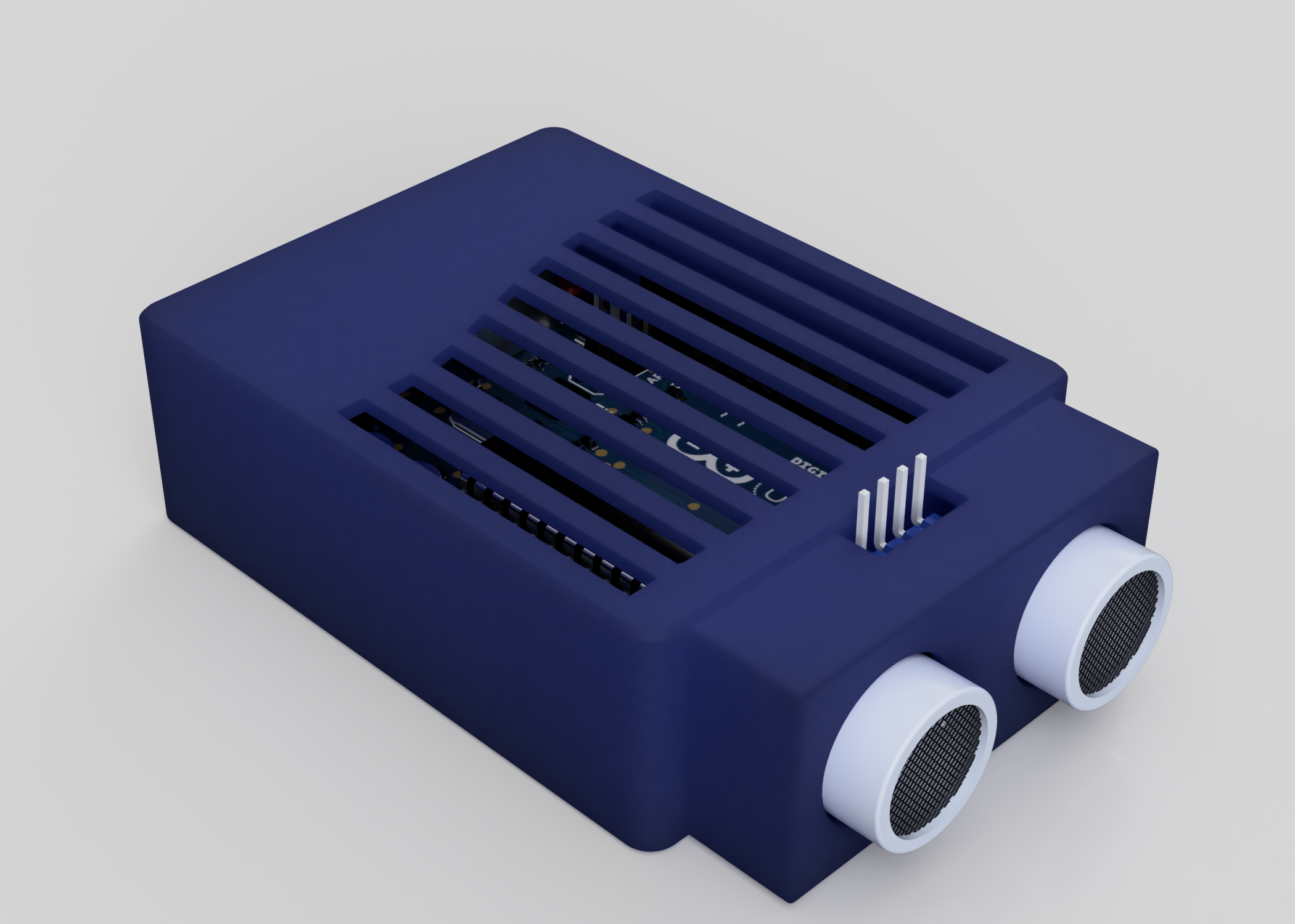
Commercial crack detectors work well, but even basic units start around €100 and professional ultrasonic flaw detectors cost far more. For EE397 at Maynooth, our group of three built a low-cost alternative: an HC-SR04 ultrasonic sensor on an Arduino Uno inside a 3D-printed enclosure. I designed the enclosure, wrote the firmware, and contributed to the research.
The firmware, CAD files and reports are on GitHub.
Starting from users, not hardware
Before designing anything, we surveyed people in construction, manufacturing and quality assurance, plus home-improvement users. The two most-wanted features were portability and low cost, ahead of severity classification and data logging. That set the brief: small, simple, cheap.
How a distance sensor finds a crack
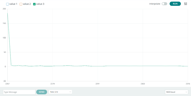
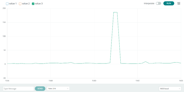
The HC-SR04 sends a 40 kHz ultrasonic pulse and measures how long the echo takes to come back. Swept across a flat surface, the distance stays constant. Over a crack, the sound travels a little further before it reflects, so the reading jumps.
The firmware is short:
float calcDistance() {
  digitalWrite(trig, LOW);
  delayMicroseconds(2);
  digitalWrite(trig, HIGH);   // 10 µs trigger pulse
  delayMicroseconds(10);
  digitalWrite(trig, LOW);

  duration = pulseIn(echo, HIGH);
  distance = (duration * 0.034) / 2;   // cm
  return distance;
}
pulseIn returns the echo time in microseconds. Sound travels about 0.034 cm per microsecond (343 m/s), and the pulse goes out and back, so the distance is half of time × speed. The loop prints a reading every 300 ms, and the Arduino IDE’s serial plotter shows it live: a flat line for a smooth surface, a spike over a crack.
| No crack | Crack detected |
|---|---|
 |  |
One thing I’d fix in the firmware: pulseIn waits up to one second by default if no echo arrives. Passing a timeout, for example pulseIn(echo, HIGH, 30000) for about 5 m of range, would stop a missed echo from freezing the device.
Checking the sensor first
The datasheet claims ±3 mm accuracy from 2 cm to 4 m. Crack detection only uses the short end, so that’s what we tested.
| Actual (cm) | Measured (cm) | Error (cm) |
|---|---|---|
| 2.0 | 1.99 | 0.01 |
| 2.5 | 2.35 | 0.15 |
| 3.0 | 3.01 | 0.01 |
| 3.6 | 3.59 | 0.01 |
| 8.0 | 7.79 | 0.21 |
The worst case was 2.1 mm, inside the datasheet’s 3 mm. We also logged readings at 0.5 and 1 cm, but those are below the sensor’s 2 cm minimum. The HC-SR04 has a blind zone there: the echo comes back before the receiver has settled after transmitting. Those numbers shouldn’t count, and in hindsight we shouldn’t have reported them.
An enclosure built from constraints
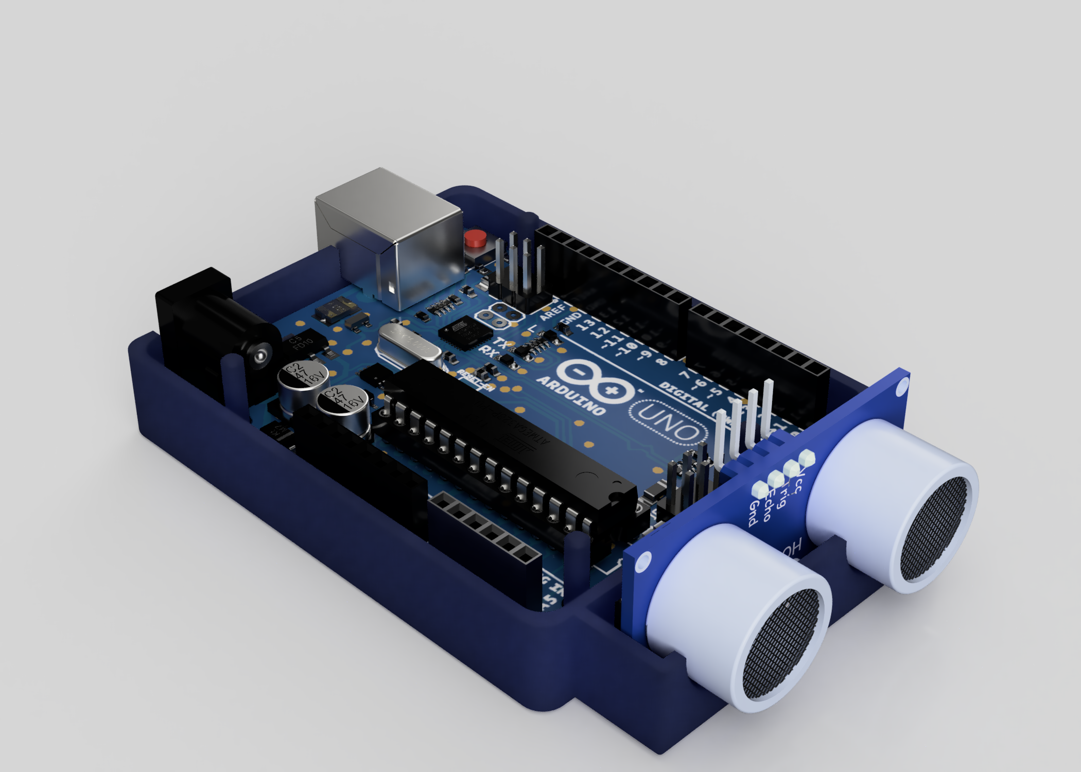
I designed the enclosure in Fusion 360 around the Arduino Uno’s footprint, as a two-part PLA snap-fit shell. Every dimension came from a manufacturing reason:
| Feature | Value | Why |
|---|---|---|
| Wall thickness | 1.6 mm | Exactly 4 perimeters with a 0.4 mm nozzle |
| Internal clearance | 1.0 mm | Allows for print shrinkage and fitting the board |
| Mounting pins | Ø2.8 mm | Under the board’s Ø3.2 mm holes: a friction fit the board can be removed from |
| Standoffs | Ø4.0 × 4.0 mm | Keeps solder joints off the floor |
| Snap-fit overlap | 4.0 mm, chamfered | Guides the halves together without cracking the print |
The sensor housing holds the transducers at a fixed position relative to the case, which matters because the sweep distance is the measurement. A cut-out exposes the programming header so the board can be reflashed without opening the case.
What users said once they held it
A second survey after building the prototype was positive about ease of use and build quality, but two new requests came up: storing readings across repeated checks, and more detailed output for reports. Both had ranked low in the first survey. They only became priorities once people had a working device in their hands, which is a good argument for building a prototype rather than designing from the first survey alone.
Honest limitations
- It detects surface geometry, not cracks. A step, a seam or a texture change produces the same spike. It only works on surfaces the user already knows should be flat.
- No severity measurement. Crack depth and width decide whether a crack matters, and a single distance reading gives neither.
- Detection is by eye. There’s no threshold, alert or logging, which are exactly the features users asked for. A rolling baseline with a deviation threshold, plus writing readings to an SD card, would be the next version.
- #arduino
- #embedded-systems
- #product-design
- #3d-printing